Contents 1. Capabilities 2. Process Cycle 3. Equipment 4. Tooling 5. Materials 6. Possible Defects 7. Design Rules 8. Cost Drivers
Process Cycle
The process cycle for injection molding is very short, typically between 2 seconds and 2 minutes, and consists of the following four stages:
Clamping - Prior to the injection of the material into the mold, the two halves of the mold must first be securely closed by the clamping unit. Each half of the mold is attached to the injection molding machine and one half is allowed to slide. The hydraulically powered clamping unit pushes the mold halves together and exerts sufficient force to keep the mold securely closed while the material is injected. The time required to close and clamp the mold is dependent upon the machine - larger machines (those with greater clamping forces) will require more time. This time can be estimated from the dry cycle time of the machine. Injection - The raw plastic material, usually in the form of pellets, is fed into the injection molding machine, and advanced towards the mold by the injection unit. During this process, the material is melted by heat and pressure. The molten plastic is then injected into the mold very quickly and the buildup of pressure packs and holds the material. The amount of material that is injected is referred to as the shot. The injection time is difficult to calculate accurately due to the complex and changing flow of the molten plastic into the mold. However, the injection time can be estimated by the shot volume, injection pressure, and injection power. Cooling - The molten plastic that is inside the mold begins to cool as soon as it makes contact with the interior mold surfaces. As the plastic cools, it will solidify into the shape of the desired part. However, during cooling some shrinkage of the part may occur. The packing of material in the injection stage allows additional material to flow into the mold and reduce the amount of visible shrinkage. The mold can not be opened until the required cooling time has elapsed. The cooling time can be estimated from several thermodynamic properties of the plastic and the maximum wall thickness of the part. Ejection - After sufficient time has passed, the cooled part may be ejected from the mold by the ejection system, which is attached to the rear half of the mold. When the mold is opened, a mechanism is used to push the part out of the mold. Force must be applied to eject the part because during cooling the part shrinks and adheres to the mold. In order to facilitate the ejection of the part, a mold release agent can be sprayed onto the surfaces of the mold cavity prior to injection of the material. The time that is required to open the mold and eject the part can be estimated from the dry cycle time of the machine and should include time for the part to fall free of the mold. Once the part is ejected, the mold can be clamped shut for the next shot to be injected.
After the injection molding cycle, some post processing is typically required. During cooling, the material in the channels of the mold will solidify attached to the part. This excess material, along with any flash that has occurred, must be trimmed from the part, typically by using cutters. For some types of material, such as thermoplastics, the scrap material that results from this trimming can be recycled by being placed into a plastic grinder, also called regrind machines or granulators, which regrinds the scrap material into pellets. Due to some degradation of the material properties, the regrind must be mixed with raw material in the proper regrind ratio to be reused in the injection molding process.
Injection molded part
Return to top
Equipment
Injection molding machines have many components and are available in different configurations, including a horizontal configuration and a vertical configuration. However, regardless of their design, all injection molding machines utilize a power source, injection unit, mold assembly, and clamping unit to perform the four stages of the process cycle.
Injection unit
The injection unit is responsible for both heating and injecting the material into the mold. The first part of this unit is the hopper, a large container into which the raw plastic is poured. The hopper has an open bottom, which allows the material to feed into the barrel. The barrel contains the mechanism for heating and injecting the material into the mold. This mechanism is usually a ram injector or a reciprocating screw. A ram injector forces the material forward through a heated section with a ram or plunger that is usually hydraulically powered. Today, the more common technique is the use of a reciprocating screw. A reciprocating screw moves the material forward by both rotating and sliding axially, being powered by either a hydraulic or electric motor. The material enters the grooves of the screw from the hopper and is advanced towards the mold as the screw rotates. While it is advanced, the material is melted by pressure, friction, and additional heaters that surround the reciprocating screw. The molten plastic is then injected very quickly into the mold through the nozzle at the end of the barrel by the buildup of pressure and the forward action of the screw. This increasing pressure allows the material to be packed and forcibly held in the mold. Once the material has solidified inside the mold, the screw can retract and fill with more material for the next shot.
Injection molding machine - Injection unit
Clamping unit
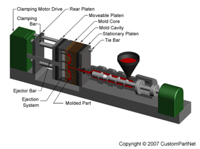
Prior to the injection of the molten plastic into the mold, the two halves of the mold must first be securely closed by the clamping unit. When the mold is attached to the injection molding machine, each half is fixed to a large plate, called a platen. The front half of the mold, called the mold cavity, is mounted to a stationary platen and aligns with the nozzle of the injection unit. The rear half of the mold, called the mold core, is mounted to a movable platen, which slides along the tie bars. The hydraulically powered clamping motor actuates clamping bars that push the moveable platen towards the stationary platen and exert sufficient force to keep the mold securely closed while the material is injected and subsequently cools. After the required cooling time, the mold is then opened by the clamping motor. An ejection system, which is attached to the rear half of the mold, is actuated by the ejector bar and pushes the solidified part out of the open cavity.
Injection molding machine - Clamping unit
Machine specifications
Injection molding machines are typically characterized by the tonnage of the clamp force they provide. The required clamp force is determined by the projected area of the parts in the mold and the pressure with which the material is injected. Therefore, a larger part will require a larger clamping force. Also, certain materials that require high injection pressures may require higher tonnage machines. The size of the part must also comply with other machine specifications, such as shot capacity, clamp stroke, minimum mold thickness, and platen size.
Injection molded parts can vary greatly in size and therefore require these measures to cover a very large range. As a result, injection molding machines are designed to each accommodate a small range of this larger spectrum of values. Sample specifications are shown below for three different models (Babyplast, Powerline, and Maxima) of injection molding machine that are manufactured by Cincinnati Milacron.
BabyplastPowerlineMaxima
Clamp force (ton)6.63304400
Shot capacity (oz.)0.13 - 0.508 - 34413 - 1054
Clamp stroke (in.)4.3323.6133.8
Min. mold thickness (in.)1.187.931.5
Platen size (in.)2.95 x 2.9540.55 x 40.55122.0 x 106.3
Injection molding machine
Return to top
Tooling
The injection molding process uses molds, typically made of steel or aluminum, as the custom tooling. The mold has many components, but can be split into two halves. Each half is attached inside the injection molding machine and the rear half is allowed to slide so that the mold can be opened and closed along the mold's parting line. The two main components of the mold are the mold core and the mold cavity. When the mold is closed, the space between the mold core and the mold cavity forms the part cavity, that will be filled with molten plastic to create the desired part. Multiple-cavity molds are sometimes used, in which the two mold halves form several identical part cavities.
Mold overview
Mold base
The mold core and mold cavity are each mounted to the mold base, which is then fixed to the platens inside the injection molding machine. The front half of the mold base includes a support plate, to which the mold cavity is attached, the sprue bushing, into which the material will flow from the nozzle, and a locating ring, in order to align the mold base with the nozzle. The rear half of the mold base includes the ejection system, to which the mold core is attached, and a support plate. When the clamping unit separates the mold halves, the ejector bar actuates the ejection system. The ejector bar pushes the ejector plate forward inside the ejector box, which in turn pushes the ejector pins into the molded part. The ejector pins push the solidified part out of the open mold cavity.
Mold base
Mold channels
In order for the molten plastic to flow into the mold cavities, several channels are integrated into the mold design. First, the molten plastic enters the mold through the sprue. Additional channels, called runners, carry the molten plastic from the sprue to all of the cavities that must be filled. At the end of each runner, the molten plastic enters the cavity through a gate which directs the flow. The molten plastic that solidifies inside these runners is attached to the part and must be separated after the part has been ejected from the mold. However, sometimes hot runner systems are used which independently heat the channels, allowing the contained material to be melted and detached from the part. Another type of channel that is built into the mold is cooling channels. These channels allow water to flow through the mold walls, adjacent to the cavity, and cool the molten plastic.
Mold channels
Mold design
In addition to runners and gates, there are many other design issues that must be considered in the design of the molds. Firstly, the mold must allow the molten plastic to flow easily into all of the cavities. Equally important is the removal of the solidified part from the mold, so a draft angle must be applied to the mold walls. The design of the mold must also accommodate any complex features on the part, such as undercuts or threads, which will require additional mold pieces. Most of these devices slide into the part cavity through the side of the mold, and are therefore known as slides, or side-actions. The most common type of side-action is a side-core which enables an external undercut to be molded. Other devices enter through the end of the mold along the parting direction, such as internal core lifters, which can form an internal undercut. To mold threads into the part, an unscrewing device is needed, which can rotate out of the mold after the threads have been formed.
Mold - Closed
Mold - Exploded view
Return to top
Materials
There are many types of materials that may be used in the injection molding process. Most polymers may be used, including all thermoplastics, some thermosets, and some elastomers. When these materials are used in the injection molding process, their raw form is usually small pellets or a fine powder. Also, colorants may be added in the process to control the color of the final part. The selection of a material for creating injection molded parts is not solely based upon the desired characteristics of the final part. While each material has different properties that will affect the strength and function of the final part, these properties also dictate the parameters used in processing these materials. Each material requires a different set of processing parameters in the injection molding process, including the injection temperature, injection pressure, mold temperature, ejection temperature, and cycle time. A comparison of some commonly used materials is shown below (Follow the links to search the material library).
Material nameAbbreviationTrade namesDescriptionApplications
AcetalPOMCelcon, Delrin, Hostaform, LucelStrong, rigid, excellent fatigue resistance, excellent creep resistance, chemical resistance, moisture resistance, naturally opaque white, low/medium costBearings, cams, gears, handles, plumbing components, rollers, rotors, slide guides, valves
AcrylicPMMADiakon, Oroglas, Lucite, PlexiglasRigid, brittle, scratch resistant, transparent, optical clarity, low/medium costDisplay stands, knobs, lenses, light housings, panels, reflectors, signs, shelves, trays
Acrylonitrile Butadiene StyreneABSCycolac, Magnum, Novodur, TerluranStrong, flexible, low mold shrinkage (tight tolerances), chemical resistance, electroplating capability, naturally opaque, low/medium costAutomotive (consoles, panels, trim, vents), boxes, gauges, housings, inhalors, toys
Cellulose AcetateCADexel, Cellidor, SetilitheTough, transparent, high costHandles, eyeglass frames
Polyamide 6 (Nylon)PA6Akulon, Ultramid, GrilonHigh strength, fatigue resistance, chemical resistance, low creep, low friction, almost opaque/white, medium/high costBearings, bushings, gears, rollers, wheels
Polyamide 6/6 (Nylon)PA6/6Kopa, Zytel, RadilonHigh strength, fatigue resistance, chemical resistance, low creep, low friction, almost opaque/white, medium/high costHandles, levers, small housings, zip ties
Polyamide 11+12 (Nylon)PA11+12Rilsan, GrilamidHigh strength, fatigue resistance, chemical resistance, low creep, low friction, almost opaque to clear, very high costAir filters, eyeglass frames, safety masks
PolycarbonatePCCalibre, Lexan, MakrolonVery tough, temperature resistance, dimensional stability, transparent, high costAutomotive (panels, lenses, consoles), bottles, containers, housings, light covers, reflectors, safety helmets and shields
Polyester - ThermoplasticPBT, PETCelanex, Crastin, Lupox, Rynite, ValoxRigid, heat resistance, chemical resistance, medium/high costAutomotive (filters, handles, pumps), bearings, cams, electrical components (connectors, sensors), gears, housings, rollers, switches, valves
Polyether SulphonePESVictrex, UdelTough, very high chemical resistance, clear, very high costValves
PolyetheretherketonePEEKEEKStrong, thermal stability, chemical resistance, abrasion resistance, low moisture absorptionAircraft components, electrical connectors, pump impellers, seals
PolyetherimidePEIUltemHeat resistance, flame resistance, transparent (amber color)Electrical components (connectors, boards, switches), covers, sheilds, surgical tools
Polyethylene - Low DensityLDPEAlkathene, Escorene, NovexLightweight, tough and flexible, excellent chemical resistance, natural waxy appearance, low costKitchenware, housings, covers, and containers
Polyethylene - High DensityHDPEEraclene, Hostalen, StamylanTough and stiff, excellent chemical resistance, natural waxy appearance, low costChair seats, housings, covers, and containers
Polyphenylene OxidePPONoryl, Thermocomp, VamporanTough, heat resistance, flame resistance, dimensional stability, low water absorption, electroplating capability, high costAutomotive (housings, panels), electrical components, housings, plumbing components
Polyphenylene SulphidePPSRyton, FortronVery high strength, heat resistance, brown, very high costBearings, covers, fuel system components, guides, switches, and shields
PolypropylenePPNovolen, Appryl, EscoreneLightweight, heat resistance, high chemical resistance, scratch resistance, natural waxy appearance, tough and stiff, low cost.Automotive (bumpers, covers, trim), bottles, caps, crates, handles, housings
Polystyrene - General purposeGPPSLacqrene, Styron, SolareneBrittle, transparent, low costCosmetics packaging, pens
Polystyrene - High impactHIPSPolystyrol, Kostil, PolystarImpact strength, rigidity, toughness, dimensional stability, naturally translucent, low costElectronic housings, food containers, toys
Polyvinyl Chloride - PlasticisedPVCWelvic, VarlanTough, flexible, flame resistance, transparent or opaque, low costElectrical insulation, housewares, medical tubing, shoe soles, toys
Polyvinyl Chloride - RigidUPVCPolycol, TrosiplastTough, flexible, flame resistance, transparent or opaque, low costOutdoor applications (drains, fittings, gutters)
Styrene AcrylonitrileSANLuran, Arpylene, StarexStiff, brittle, chemical resistance, heat resistance, hydrolytically stable, transparent, low costHousewares, knobs, syringes
Thermoplastic Elastomer/RubberTPE/RHytrel, Santoprene, SarlinkTough, flexible, high costBushings, electrical components, seals, washers
Return to top
Possible Defects
DefectCauses
FlashInjection pressure too high Clamp force too low
WarpingNon-uniform cooling rate
BubblesInjection temperature too high Too much moisture in material Non-uniform cooling rate
Unfilled sectionsInsufficient shot volume Flow rate of material too low
Sink marksInjection pressure too low Non-uniform cooling rate
Ejector marksCooling time too short Ejection force too high
Many of the above defects are caused by a non-uniform cooling rate. A variation in the cooling rate can be caused by non-uniform wall thickness or non-uniform mold temperature.
Return to top
Design Rules
Maximum wall thickness
Decrease the maximum wall thickness of a part to shorten the cycle time (injection time and cooling time specifically) and reduce the part volume
INCORRECT
Part with thick walls
CORRECT
Part redesigned with thin walls
Uniform wall thickness will ensure uniform cooling and reduce defects
INCORRECT
Non-uniform wall thickness (t1 ≠ t2)
CORRECT
Uniform wall thickness (t1 = t2)
Corners
Round corners to reduce stress concentrations and fracture Inner radius should be at least the thickness of the walls
INCORRECT
Sharp corner
CORRECT
Rounded corner
Draft
Apply a draft angle of 1° - 2° to all walls parallel to the parting direction to facilitate removing the part from the mold.
INCORRECT
No draft angle
CORRECT
Draft angle (q)
Ribs
Add ribs for structural support, rather than increasing the wall thickness
INCORRECT
Thick wall of thickness t
CORRECT
Thin wall of thickness t with ribs
Orient ribs perpendicular to the axis about which bending may occur
INCORRECT
Incorrect rib direction under load F
CORRECT
Correct rib direction under load F
Thickness of ribs should be 50-60% of the walls to which they are attached Height of ribs should be less than three times the wall thickness Round the corners at the point of attachment Apply a draft angle of at least 0.25°
INCORRECT
Thick rib of thickness t
CORRECT
Thin rib of thickness t
Close up of ribs
Bosses
Wall thickness of bosses should be no more than 60% of the main wall thickness Radius at the base should be at least 25% of the main wall thickness Should be supported by ribs that connect to adjacent walls or by gussets at the base.
INCORRECT
Isolated bossCORRECT
Isolated boss with ribs (left) or gussets (right)
If a boss must be placed near a corner, it should be isolated using ribs.
INCORRECT
Boss in corner
CORRECT
Ribbed boss in corner
Undercuts
Minimize the number of external undercuts External undercuts require side-cores which add to the tooling cost Some simple external undercuts can be molded by relocating the parting line
Simple external undercut
Mold cannot separate
New parting line allows undercut
Redesigning a feature can remove an external undercut
Part with hinge
Hinge requires side-core
Redesigned hinge
New hinge can be molded
Minimize the number of internal undercuts Internal undercuts often require internal core lifters which add to the tooling cost Designing an opening in the side of a part can allow a side-core to form an internal undercut
Internal undercut accessible
from the side
Redesigning a part can remove an internal undercut
Part with internal undercut
Mold cannot separate
Part redesigned with slot
New part can be molded
Minimize number of side-action directions Additional side-action directions will limit the number of possible cavities in the mold
Threads
If possible, features with external threads should be oriented perpendicular to the parting direction. Threaded features that are parallel to the parting direction will require an unscrewing device, which greatly adds to the tooling cost.
Return to top
Cost Drivers
Material cost
The material cost is determined by the weight of material that is required and the unit price of that material. The weight of material is clearly a result of the part volume and material density; however, the part's maximum wall thickness can also play a role. The weight of material that is required includes the material that fills the channels of the mold. The size of those channels, and hence the amount of material, is largely determined by the thickness of the part.
Production cost
The production cost is primarily calculated from the hourly rate and the cycle time. The hourly rate is proportional to the size of the injection molding machine being used, so it is important to understand how the part design affects machine selection. Injection molding machines are typically referred to by the tonnage of the clamping force they provide. The required clamping force is determined by the projected area of the part and the pressure with which the material is injected. Therefore, a larger part will require a larger clamping force, and hence a more expensive machine. Also, certain materials that require high injection pressures may require higher tonnage machines. The size of the part must also comply with other machine specifications, such as clamp stroke, platen size, and shot capacity.
The cycle time can be broken down into the injection time, cooling time, and resetting time. By reducing any of these times, the production cost will be lowered. The injection time can be decreased by reducing the maximum wall thickness of the part and the part volume. The cooling time is also decreased for lower wall thicknesses, as they require less time to cool all the way through. Several thermodynamic properties of the material also affect the cooling time. Lastly, the resetting time depends on the machine size and the part size. A larger part will require larger motions from the machine to open, close, and eject the part, and a larger machine requires more time to perform these operations.
Tooling cost
The tooling cost has two main components - the mold base and the machining of the cavities. The cost of the mold base is primarily controlled by the size of the part's envelope. A larger part requires a larger, more expensive, mold base. The cost of machining the cavities is affected by nearly every aspect of the part's geometry. The primary cost driver is the size of the cavity that must be machined, measured by the projected area of the cavity (equal to the projected area of the part and projected holes) and its depth. Any other elements that will require additional machining time will add to the cost, including the feature count, parting surface, side-cores, lifters, unscrewing devices, tolerance, and surface roughness.
The quantity of parts also impacts the tooling cost. A larger production quantity will require a higher class mold that will not wear as quickly. The stronger mold material results in a higher mold base cost and more machining time.
One final consideration is the number of side-action directions, which can indirectly affect the cost. The additional cost for side-cores is determined by how many are used. However, the number of directions can restrict the number of cavities that can be included in the mold. For example, the mold for a part which requires 3 side-action directions can only contain 2 cavities. There is no direct cost added, but it is possible that the use of more cavities could provide further savings.
Return to top
About CustomPartNet
About Us Contact Us Privacy Policy List Your Company Advertise
Process Overviews
Injection Molding Sand Casting Milling Die Casting Glossary
Cost Estimators
Injection Molding Estimator Machining Estimator Die Casting Estimator Sand Casting Estimator . . . see all estimators
Widgets
Speed and Feed Calculator Drill Size/Tap Size Chart Clamping Force Calculator Volume/Weight Calculator . . . see all widgets
Copyright ? 2009 CustomPartNet. All Rights Reserved.