Table of Contents
Table of Contents TOC-1
Section 1 - Foreword 1-1
Section 2 - FMEA General Information 2-1
Section 3 - Design FMEA (DFMEA) 3-1
Section 4 - Process FMEA (PFMEA) 4-1
Section 5 - Concept FMEA (CFMEA) 5-1
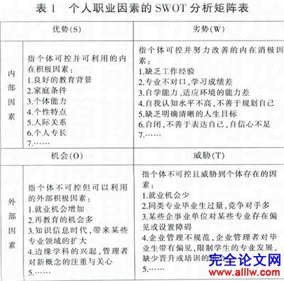
Section 6 - Special Characteristics 6-1
Appendix A - FMEA Forms A-1
Appendix B - Helpful Tools for FMEA B-1
Appendix C - FMEA Checklist C-1
Appendix D - Automotive Procedures (FAPs) D-1
Appendix E - FMEA Applications E-1
Glossary Glossary-1
Description See Page
FMEA Handbook Organization 1-2
Common Questions
What Is the Purpose of this FMEA Handbook? 1-3
Can this FMEA Handbook be Given to Suppliers? 1-3
What Does this FMEA Handbook Contain? 1-3
Can the Guidelines Given in this FMEA Handbook be
Supplemented?
1-4
FMEA Handbook Provenance 1-4
What Can I Read to Obtain More Background on FMEAs? 1-4
Where Can I Find More Information on Special
Characteristics?
1-5
Why Does the Handbook Need a Revision? 1-5
What's New in the 2004 Update? 1-5
About this FMEA Handbook
In this FMEA Handbook 1-7
Section Title Contents
1 Foreword Provides general information about the FMEA
Handbook.
2 FMEA General
Information
Provides general information about the FMEA
process.
3 Design FMEA
(DFMEA)
Explains the Design FMEA process.
4 Process FMEA
(PFMEA)
Explains the Process FMEA process.
5 Concept FMEA
(CFMEA)
Explains the Design Concept or Process
Concept FMEA process.
6 Special
Characteristics
Shows how FMEAs are used to identify
Special Characteristics.
Appendix A: FMEA Forms
Appendix B: Helpful Tools for FMEA
Appendix C: FMEA Checklist
Appendix D:CORP Automotive Procedures(CAPs)
Appendix E: FMEA Applications
Glossary
This FMEA Handbook introduces Failure Mode and EffectsAnalysis
(FMEA) as defined by the Society of Automotive Engineers (SAE)and
gives specific requirements for FMEAs.
Any italicized text quotes the SAE J1739 (Revised August2002)
standard.
You can use this FMEA Handbook:
• To learn the basics of FMEA
• As a reference tool, after training
• To assist in the writing, preparation, review, and editing ofFMEAs
This FMEA Handbook is also intended to be used as a guide in
deploying the Special Characteristics Operating System: i.e., toassist
engineering teams worldwide to identifyproduct/process
characteristics important to product safety, regulatoryconformance,
and customer quality. Specifically, the FMEA Handbook is intendedto
help deploy the policy and principles embodied in Automotive
Procedure – CAP 03-111.
This FMEA Handbook contains instructions for preparing anFMEA,
and answers the What, Why, When, Who and How regarding FMEA
methodologies. This FMEA Handbook shows how to conduct three
types of FMEAs:
• Design FMEA
• Process FMEA
• Concept FMEA
Additionally, special applications of the three FMEA typesare
presented as examples. These special applications aremachinery,
environment, and software.
This FMEA Handbook provides additional specific informationfor
the creation of FMEAs. The most notable areas to referenceare:
• Concept FMEA
• Designations for the Classification column
• Reduced emphasis on RPN, emphasis on Severity, the Severity
times Occurrence (Criticality), then RPN (Severity x Occurrencex
Detection)
• The inclusion of Robustness Tools in the FMEA process
This FMEA Handbook introduces the topic of potential FMEAand
gives general guidance in applying the technique. FMEAtechniques
are continually being improved. Additional actions to improvethe
FMEA techniques may be implemented by the people preparingthe
FMEA. However, these actions should not undermine FMEA
objectives.
This FMEA Handbook is consistent with the SAE Recommended
Practice, SAE J1739 – "Potential Failure Mode and Effects Analysisin
Design (Design FMEA) and Potential Failure Mode and Effects
Analysis in Manufacturing and Assembly Processes (ProcessFMEA),
and Potential Failure Mode and Effects Analysis for Machinery
(Machinery FMEA)” revision.
DaimlerChrysler, Ford Motor Company, and General Motorsjointly
developed the first release of this practice under the sponsorshipof
the United States Council for Automotive Research (USCAR).SAE
J1739 gives general guidance in the application of thetechnique.
DaimlerChrysler, Ford Motor Company, and General Motors
representatives to the SAE have worked together to completethe
latest revision of the SAE standards dated August 2002.
For more information or for a copy of J1739, visit:
http://www.sae.org/
Ford/GM/DaimlerChrysler Advance Product Quality Planningand
Control Plan Reference (APQP)
Ford/GM/DaimlerChrysler Quality System-9000 (QS-9000)
AIAG http://www.aiag.org/
SAE http://www.sae.org/
CAP 03 –111 – Selection and Identification of Significant andCritical
Characteristics. Throughout Sections 2 through 5 of thishandbook,
the term Special Characteristics is used to denote thosedesignated
characteristics like YC and YS in DFMEA and ∇ (sometimesreferred
to as CC) and SC in PFMEA. Refer to Section 6 for detailed
discussion of these and other types of Special Characteristics.
Keep the handbook consistent with the industrial standard -new
SAE J1739 was published in August, 2002, and a 2-column
design control FMEA form is recommended.
• Improve the quality of the handbook - many recommendation,
suggestions, and corrections have been received from experts,
engineers, and suppliers since the publication of theprevious
version. The revision focused on achieving:
o better flow of the contents;
o better and clearer examples, definitions, and procedures;and
o elimination of the inconsistencies and errors.
The Version 4.1 minor update includes cosmetic updates andaddition
of an index. The Version 4.0 update included the followingchanges:
The FMEA flow chart has been updated according to FAP 07-005-
Vehicle Program Quality/Reliability/Robustness Planning. Thenew
chart not only illustrated the information flow in the process ofFMEA
development, but also defines the role of FMEA in the failuremodes
avoidance. FMEA focuses on preventing mistakes, while as the
Robustness Engineering Design Product Enhancement Process
(REDPEPR) focuses on improving product robustness
SAE J1739
August 2002
The new SAE J1739 FMEA forms are introduced, and
all the examples have been modified using the new
form.
Simplified
FMEA
Checklist
This version of the handbook consolidated the "FMEA
Checklist", the "Design FMEA Checklist", the "Process
FMEA Checklist", and the "FMEA Quick Reference" of
the previous version into a simplified FMEA Checklist
given in Appendix C.
Revised
Examples
Revised examples are included in the Design FMEA
sections.
FAP
Reference
The documents of FAP 07-005, and FAP 03-111 have
been removed from the handbook. Instead, only the
web addresses of the FAPs are given for the
references.
Concept
FMEA
The "Concept FMEA" section has been moved from
Section 3 in the previous version to Section 5 in this
version after the "Design FMEA" and "Process FMEA"
sections.
Updated
Glossary
The Glossary has been updated.
System
Interface
Analyzer
(SIA)
A tool for analyzing the system interfaces, developing
the system Boundary Diagram and Interface Matrix
has been briefly introduced. For more information,
please visit:
Description See Page
FMEA Definition 2-3
FMEA Implementation 2-4
FMEA Purposes 2-5
General Benefits
General Benefits 2-6
Best Practice FMEA 2-6
Types of FMEAs
Types of FMEAs 2-7
Machinery Note 2-7
FMEA Flow and its Role in Failure Mode Avoidance (Robustness
Linkages)
2-8
FMEA Flow (Robustness Linkages) 2-8
Useful Information Sources for Input to FMEA 2-10
FMEA Provides Input to 2-10
Change Point Approach
FMEA Change Point Approach 2-11
Benefits of FMEA Types
Concept FMEA Benefits and Uses 2-12
Concept FMEA Outputs 2-12
Design FMEA Benefits and Uses 2-13
Design FMEA Outputs 2-14
Process FMEA Benefits and Uses 2-15
Process FMEA Outputs 2-16
Description See Page
(Continued) Generating FMEAs
Who Initiates an FMEA? 2-17
Who Prepares an FMEA? 2-17
Who Updates an FMEA? 2-18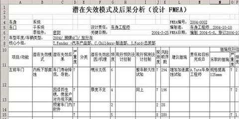
How do I Start or Update an FMEA? 2-18
When is an FMEA Started or Updated? 2-19
FPDS Timings 2-20
Who is the FMEA Customer? 2-20
When is an FMEA Completed? 2-21
How are FMEA Results Documented? 2-21
When Can FMEA Documents be Discarded? 2-21
Systems Engineering Relationships
FMEAs Related to Systems Engineering 2-22
Systems Engineering Fundamentals 2-22
APQP Relationship 2-22
An FMEA can be described as a systemized group of activitiesintended to:
(a) recognize and evaluate the potential failure of aproduct/process and its
effects,
(b) identify actions which could eliminate or reduce the chance ofthe
potential failure occurring, and
(c) document the process. It is complementary to the process ofdefining
what a design or process must do to satisfy the customer.
FMEAs identify potential and confirm Critical and Significant
Characteristics to be addressed by design changes, processchanges,
or inclusion in Process Control Plans.
FMEAs evaluate the adequacy of proposed controls and the needto
mitigate risk by changes to the Design Verification Plan orthe
Manufacturing Control Plan. The intent of the evaluation andthe
proposed actions is to prevent failures from reaching thecustomers,
improving customer satisfaction.
For more information on Control Plans, refer to Appendix pageB-31.
Because of the general industry trend to continually improveproducts and
processes whenever possible, using the FMEA as a disciplinedtechnique to
identify and help minimize potential concern is as important asever. Studies
of vehicle campaigns have shown that fully implemented FMEAprograms
could have prevented many of the campaigns.
One of the most important factors for the successful implementationof an
FMEA program is timeliness. It is meant to be a "before-the-event"action,
not an "after-the-fact" exercise. To achieve the greatest value,the FMEA
must be done before a product or process Failure Mode hasbeen
incorporated into a product or process. Up front time spentproperly
completing an FMEA, when product/process changes can be most easilyand
inexpensively implemented, will minimize late change crises. AnFMEA can
reduce or eliminate the chance of implementing apreventive/corrective
change, which would create an even larger concern. Communicationand
coordination should occur between all types of FMEAs.
Studies performed withinCORP have shown thatsignificant savings in
engineering time and other costs could have been realized ifFMEAs
were completed according to the FMEA "Best Practices."
General/overall purposes of an FMEA:
• Improves the quality, reliability and safety of theevaluated
products/processes.
• Reduces product redevelopment timing and cost.
• Documents and tracks actions taken to reduce risk.
• Aids in the development of robust control plans.
• Aids in the development of robust design verificationplans.
• Helps engineers prioritize and focus oneliminating/reducing
product and process concerns and/or helps prevent problemsfrom
occurring.
• Improves customer/consumer satisfaction.
FMEA purposes:
• Identifies Special Characteristics (Critical Characteristicsand
Significant Characteristics).
• Acts as a “lessons learned” input to System DesignSpecifications
(SDS), Design Verification Plans (DVP), control plans, design
guides, and other documents and procedures.
• Includes Robustness Tools in the FMEA process.
A series of FMEAs completed according to the best practice couldact
on the noise factors shown in this illustration. A best practiceFMEA
series might be described as:
• Doing FMEAs at the right time
• Considering all interfaces and "noise factors" (shown on a
P-Diagram and Interface matrix)
• Starting FMEAs at the system level and cascading informationand
requirements down to Component and Process FMEAs
• Using appropriate Recommended Actions to mitigate risk
• Completing all Recommended Actions in a timely manner
recognizes the following types of FMEAs:
• Concept FMEA (CFMEA): performed on
designs and processes
o System CFMEA
o Sub-system CFMEA
o Component CFMEA
• Design FMEA (DFMEA): Standardized industry-wide
o System DFMEA
o Sub-system DFMEA
o Component DFMEA
• Process FMEA (PFMEA - Assembly, Manufacturing):
Standardized industry-wide
o System PFMEA
o Sub-system PFMEA
o Component PFMEA
• Machinery: As a Design FMEA application
Preventing mistakes and improving robustness are two distinct,but
complementary efforts in failure mode avoidance. Each of themhas
its own focus and strength.
The above flow chart illustrates the information flow when an
engineering team performs a FMEA. The downward arrowsrepresent
the main flow and the upward arrows represent lessons learnedand
feedback. The two way arrow represents interfaces between aFMEA
and REDPEPR (Robustness Engineering Design and Product
Enhancement Process). The key tasks are:
Boundary Diagram – Defines the system boundary/scope and
clarifies the relationship between the focused system and its
interfacing systems.
Interface Matrix – Identifies system interfaces and both theeffects of
interfaces to the focused system and the interfacing systems.It
documents system interface details.
FMEA Flow and its Role In Failure Mode Avoidance
(Robustness Linkages), Continued
The Quality History is always an important input. Past qualityissues
need close attention to prevent reoccurrence.
FMEA Flow
(Robustness
Linkages)
(Continued) DFMEA is a thorough and detail analysis of thepotential failure modes
(soft and hard failures) related to the system primary functionsand
interface functions. DFMEA is the primary document forcapturing
tests that are required to demonstrate we have avoided mistakes.It
analyzes and prioritizes the effects and causes of failuremode
actions. DFMEA identifies current controls and additional actionsto
reduce associated risks.
As a complementary effort Robustness Engineering (REDPEPR)
includes:
1. P-Diagram – identifies and documents the input signal(s),noise
factors, control factors, and error states as associated withthe
ideal function(s).
2. Robustness Check List (RCL) is an in-depth analysis ofnoise
factor impact to the ideal function(s) and error states. It isa
methodical assessment of the effectiveness of available DVMs
(Design Verification Methods) in terms of noise factor coverage.It
generates noise factor management strategies.
3. Robustness Demonstration Matrix (RDM) is a data driven
approach to ensure the tests the noise factors, and testmetrics
are measured/quantified to prove out the robustness. RDM is a
part of Design Verification Plan (DVP).
DFMEA and Robustness Engineering are complementary. For
example, noise factors assist failure cause identification anderror
states provide input to failure mode and effect identification.More
importantly, the outcomes from REDPEPR become knowledge and
need to be institutionalized for future mistake prevention.Conversely,
high risk failure modes identified in the FMEA may need to be
analyzed in-depth using REDPEPR.
Design Verification Plan (DVP) – is a comprehensive design
verification plan that incorporates inputs from both DFMEAand
REDPEPR. It ensures that the noise factors are included in testsand it
addresses the critical measurables for evaluation of idealfunctions
and potential/anticipated failure modes during and after thetests.
The following process elements/tools may provide input tothe
DFMEA:
• Requirements (WCR, Corporate, Regulatory, etc.)
• SDS
• QFDs
• Historical performance information
• Benchmarking data
• Pre-PD targets
• P-Diagram
o Ideal Functions as Functions
o Error States as Failure Modes or Effects of Failure
o Control Factors may help in identifying Design Controls or
Recommended Actions
• Boundary Diagram and Interface Matrix
o Intended outputs as Functions
o System interactions may help in identifying Cause(s) ofFailure
FMEA Provides
Input to:
• DVP
• Robustness Checklist
• Critical/Significant Characteristics
• System/Subsystem/Component design specifications
• Validation criteria
• Safety sign-off
• Control plans
There are three basic cases for which FMEAs are generated, eachwith a
different scope or focus:
Case 1: New designs, new technology, or new process. The scope ofthe
FMEA is the complete design, technology or process.
Case 2: Modifications to existing design or process (assumes thereis a
FMEA for the existing design or process). The scope of theFMEA
should focus on the modification to design or process,possible
interactions due to the modification, and field history.
Case 3: Use of existing design or process in a new environment,location or
application (assumes there is an FMEA for the existing designor
process). The scope of the FMEA is the impact of the new
environment or location on the existing design or process.
The benefits of doing a Concept FMEA include:
• Helps select the optimum concept alternatives, or determine
changes to System Design Specifications (SDS).
• Identifies potential Failure Modes and Causes due tointeractions
within the concept.
• Increases the likelihood all potential effects of aproposed
concept’s Failure Modes are considered.
• Helps generate Cause Occurrence ratings that can be used to
estimate a particular concept alternative’s target.
• Identifies system and subsystem level testing requirements.
• Helps determine if hardware system redundancy may berequired
within a design proposal.
• Focuses on potential Failure Modes associated with theproposed
functions of a concept proposal caused by design decisionsthat
introduce deficiencies (these include "design" decisions aboutthe
process layout).
• Include the interaction of multiple systems and theinteraction
between the elements of a system at concept stages (this maybe
operation interaction in the process).
The outputs of a Concept FMEA include:
• A list of potential concept Failure Modes and Causes.
• A list of design actions to eliminate the causes of FailureModes,
or reduce their rate of occurrence.
• Recommended changes to SDSs.
• Specific operating parameters as key specifications in thedesign.
• Changes to global manufacturing standards or procedures.
• New test methods or recommendations for new generictesting.
• Decision on which concept to pursue.
The Design FMEA supports the design process in reducing the riskof
failures (including unintended outcomes) by:
• Aiding in the objective evaluation of design, includingfunctional
requirements and design alternatives.
• Evaluating the initial design for manufacturing, assembly,service, and
recycling requirements.
• Increasing the probability that potential Failure Modes and theireffects
on system and vehicle operation have been considered in the
design/development process.
• Providing additional information to aid in the planning ofthorough and
efficient design, development, and validation programs.
• Developing a ranked list of potential Failure Modes according totheir
effect on the "customer," thus establishing a priority system fordesign
improvements, development and validation testing/analysis.
• Providing an open issue format for recommending and trackingrisk
reducing actions.
• Providing future reference, e.g., lessons learned, to aid inanalyzing field
concerns, evaluating design changes and developing advanceddesigns.
• Helping identify potential Critical Characteristics andpotential
Significant Characteristics.
• Helping validate the Design Verification Plan (DVP) and the
System Design Specifications (SDSs).
• Focusing on potential Failure Modes of products caused bydesign
deficiencies.
• Identifying potential designated characteristics, calledSpecial
Characteristics.
The outputs of a Design FMEA include:
• A list of potential product Failure Modes and Causes.
• A list of potential Critical Characteristics and/orSignificant
Characteristics.
• A list of recommended actions for reducing severity,eliminating
the causes of product Failure Modes or reducing their rate of
Occurrence, or improving Detection.
• For system-level Design FMEAs, confirmation of the SDSs or
updates required for SDSs.
• Confirmation of the Design Verification Plan (DVP).
• Feedback of design changes to the design committee.
The benefits of doing a Process FMEA include:
• Identifies the process functions and requirements
• Identifies potential product and process related FailureModes.
• Assesses the effects of the potential failures on thecustomer,
• Identifies the potential manufacturing or assembly process causesand
identifies process variables on which to focus controls foroccurrence
reduction or detection of the failure conditions.
• Identifies process variables on which to focus processcontrols
• Develops a ranked list of potential Failure Modes, thusestablishing a
priority system for preventative/ corrective action considerations,and
• Documents the results of the manufacturing or assemblyprocess.
• Identifies process deficiencies to enable engineers to focuson
controls for reducing the occurrence of producingunacceptable
products, or on methods to increase the detection ofunacceptable
products.
• Identifies confirmed Critical Characteristics and/orSignificant
Characteristics.
• Aiding in development of thorough manufacturing or assembly
control plans.
• Identifies operator safety concerns.
• Feeds information on design changes required andmanufacturing
feasibility back to the design community.
• Focusing on potential product Failure Modes caused by
manufacturing or assembly process deficiencies.
• Confirming the need for Special Controls in manufacturing,and
confirming the designated potential "Special Characteristics"from
the Design FMEA (DFMEA).
• Identifying process Failure Modes that could violategovernment
regulations or compromise employee safety.
• Identifying other Special Characteristics – Operator Safety(OS)
and High Impact (HI).
The outputs of a Process FMEA include:
• A list of potential process Failure Modes.
• A list of confirmed Critical Characteristics and/orSignificant
Characteristics.
• A list of Operator Safety and High Impact Characteristics.
• A list of recommended Special Controls for designatedproduct
Special Characteristics to be entered on a control plan.
• A list of processes or process actions to reduce Severity,eliminate
the Causes of product Failure Modes or reduce their rate of
Occurrence, and to improve product defect Detection ifprocess
capability cannot be improved.
• Recommended changes to process sheets and assembly aid
drawings.
...